Outdoor Fireplace Specs are the difference between a code-compliant installation and a site that ends up with water-driven stone failures, emergency repairs, and warranty claims that cut margins and stretch schedules.
This guide functions as a technical SOP for exterior stacked stone fireplaces: we cover substrate and adhesion requirements, waterproofing stone veneer chimney assemblies, the role of drip caps and flashing, freeze-thaw stone detailing to prevent spalling, selecting UV-stable mineral pigments for long-term color stability, and practical maintenance for moss and algae. Expect actionable spec callouts, recommended ASTM and manufacturer references, and field detailing that link material selection to long-term performance so design, construction, and maintenance teams can reduce failure risk on projects of any scale.
Why Outdoor Fireplaces Demand Different Stone and Adhesion Specs?
Outdoor fireplaces need noncombustible, freeze‑thaw‑stable stone and high‑temperature bonding to meet codes and avoid rapid weather or thermal failure.
Stone selection and panel specifications for exterior fire exposures
Specify 100% natural quartzite or slate for veneers that face direct heat and weather; choose quartzite when you need the highest resistance to thermal cycling, freeze‑thaw and salt spray. Size panels and finishes to match exposure: standard veneers perform well at 10–25 mm thickness, while rough or premium panels intended for directly exposed hearth facades should be 25–35 mm. Design substrate and supports for the actual panel weight—plan roughly 30–40 kg/m² for flat panels and up to 55 kg/m² for rough stacked installations to avoid settlement or pull‑out.
Use interlocking Z‑Shape or S‑Shape panels and matching L‑corners to reduce visible joints and limit heavy mortaring at corners; CNC diamond‑blade precision improves male‑female fit and speeds field assembly. For large elevations, source material from the same quarry vein to hold hue uniformity near 95%, and specify UV‑stable, high salinity/humidity resistant stone for coastal and Gulf climates to prevent surface degradation.
- Recommended stone: 100% natural quartzite or slate; quartzite for highest durability.
- Panel thickness: 10–25 mm (standard), 25–35 mm (rough/premium).
- Design weights: ~30–40 kg/m² (flat), up to 55 kg/m² (rough stacked).
- Panel sizes typically used: 150×600 mm (6″×24″) or 150×550 mm (6″×22″).
- Specify same‑batch quarry sourcing (~95% hue uniformity) and UV‑stable finishes for high‑sun or coastal exposure.
Adhesion methods and high‑temperature bedding for firebox and veneer interfaces
Managing Freeze-Thaw Cycles in Exterior Natural Stone Surrounds
Selecting low‑porosity stone, engineered attachment and a drainable substrate stops freeze‑thaw failures and lowers long‑term repairs.
Select stone and verify freeze‑thaw suitability
Select quartzite or slate for the highest freeze‑thaw resistance; use granite when mass and thermal stability matter, and avoid or treat highly porous stones such as certain sandstones and marble. Require your supplier to declare ASTM‑standard freeze‑thaw resistance and to source panels from the same quarry vein to meet 95% hue uniformity—this reduces patching and thermal stress concentration across large elevations.
Dry‑fit a representative mockup and run a controlled wetting/drying trial to reveal delamination, staining or mortar migration before full installation. Use the mockup to confirm panel handling, joint geometry and finish match under real weather cycles, then document results and accept/reject criteria in writing.
- Panel sizes: 150 x 600 mm or 150 x 550 mm.
- Thickness: 1.0–2.5 cm standard; up to 3.5 cm for rough/premium panels.
- Weight: ~30–40 kg/m² (flat); ~55 kg/m² (rough).
- Supplier deliverable: ASTM freeze‑thaw test report + same‑batch quarry declaration.
Prepare substrate, drainage plane and movement joint layout
Calculate dead loads using panel weights (30–55 kg/m²) and design fixings, substrate framing and anchors to handle those loads plus applicable live loads and wind uplift. Size backer studs, masonry ties or metal framing per local code and the combined load; confirm substrate fastener pull‑out values exceed calculated design loads with an appropriate safety factor.
Provide a continuous drainage plane behind the veneer, terminate flashing at transitions, and create continuous weep/vent paths so trapped moisture leaves the cavity. Place movement joints at all plane changes and along long uninterrupted runs—determine joint spacing and width through project engineering to accommodate thermal expansion and substrate movement. Remove combustible substrates behind stone and verify substrate flatness and compatibility with the chosen adhesive or anchor system before fixing panels.
- Design note: use 30–55 kg/m² as dead‑load basis for substrate and anchor sizing.
- Drainage: continuous cavity, flashing upturns, and bottom weeps at 600–900 mm intervals where practical.
- Movement joints: place at every change of plane, at floor lines and where façade length exceeds engineered spacing.
- Substrate check: confirm flatness tolerance and remove combustibles behind veneer.
Specify adhesives, anchors and compatibility for freeze‑thaw cycles
Specify a polymer‑modified, exterior‑rated mortar or adhesive that lists freeze‑thaw durability and high bond strength; follow the manufacturer’s trowel size, open time and conditioning instructions. For sealant work on horizontal transitions select a weatherproof silicone rated for extreme climates (for example, products with service ranges comparable to GE Silicone II: roughly -51°C to +95°C) and allow full cure—typically 24 hours—before subjecting joints to weather.
Use corrosion‑resistant mechanical anchors (stainless steel or hot‑dip galvanized) sized and spaced for panel weight and local code. Back‑butter panels where necessary to eliminate voids and ensure full bedding contact; voids trap water and accelerate freeze damage. Verify chemical compatibility among adhesive, primer and sealant to avoid bond failure or staining of natural stone.
- Adhesive: polymer‑modified mortar, freeze‑thaw rated; follow trowel and open‑time specs.
- Sealant: exterior silicone with wide service temperature range; allow 24 hr full cure before exposure.
- Anchors: stainless or hot‑dip galvanized; specify embed depth and spacing per panel weight and code.
- Installation control: back‑butter to eliminate voids and check full contact at each panel.
- Compatibility: require lab or manufacturer confirmation that adhesives, primers and sealants suit the stone chemistry.
Install interlocking panels and corners to minimize water ingress
Use Z‑Shape or S‑Shape interlocking panels with CNC diamond‑blade precision edges to hide vertical joints and reduce exposed joint area. Start at the bottom and work upward, fully engage the male/female interlocks, and stagger vertical seams to distribute movement and avoid continuous vertical weak lines. Fit matching L‑corners to maintain continuous texture and color at corners and terminations.
Detail horizontal transitions and penetrations with a flexible exterior sealant and avoid trapping mortar or substrate behind interlocks. Dry‑fit each run, check for gaps, rocking or misalignment, then adjust before adhesive cures to prevent post‑cure corrective work.
- Fit order: bottom to top; engage male/female fully; stagger vertical seams.
- Use CNC‑cut edges to maintain tight joints and reduce exposed mortar faces.
- Seal horizontal terminations and penetrations with flexible exterior sealant; leave drainage paths clear.
- Perform dry‑fit quality control and correct alignment before adhesive cures.
Seal, verify performance and establish inspection schedule
Apply a breathable penetrating sealer rated for UV, salinity and freeze‑thaw exposure; select products that do not change slip or color and that the stone manufacturer approves. Test sealer performance with a 30‑minute water bead test and document results; reseal at manufacturer intervals—typically every 12–24 months for exterior fireplace surrounds depending on exposure and stone porosity.
Conduct field verification after installation with water ponding and spray tests to confirm drainage, sealant adhesion and absence of leaks; photograph and record measurements. Inspect the installation after the first winter and then at least annually for cracking, spalling, efflorescence and sealant failures. Clean biological growth with approved cleaners, replace failed sealant joints, and tighten or replace any corroded anchors immediately to prevent progressive freeze‑thaw damage.
- Sealer: breathable penetrating product rated for UV and salinity; reapply every 12–24 months or per manufacturer.
- Field tests: water ponding and spray tests; document photos and measurements.
- Inspection schedule: after first winter, then annually; inspect for cracking, spalling, efflorescence and sealant failure.
- Maintenance: remove moss/algae with approved cleaners, replace failed joints, and replace corroded anchors promptly.
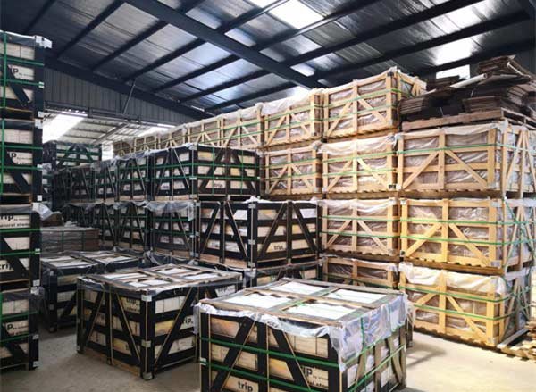
Premium Stacked Stone, Faster Installs
Waterproofing the Chimney Structure Before Applying Stone Veneer
Protect the chimney envelope before veneer to prevent moisture intrusion, structural damage, and costly rework on exterior fireplaces.
Assess substrate, load capacity and clearance before waterproofing
Start by documenting the substrate: identify masonry chase, framed chase with sheathing, or steel construction and record material type and thickness. Size the support system to the expected dead load: Top Source standard stacked stone runs about 30–40 kg/m² (8–12 lb/ft²), while rough panels can approach 55 kg/m²; use those numbers to specify shelf angles or structural framing and verify the shelf angle design with an engineer. Confirm required clearances to flues and combustibles per local code and the fireplace manufacturer—masonry installations commonly require a 1 in clearance to combustibles—and record any reduced-clearance options for rated assemblies.
- Document substrate type, sheathing thickness, and any insulation or air gaps.
- Use 30–40 kg/m² for standard panels, 55 kg/m² for rough panels when specifying shelf angles or framing.
- Verify minimum clearances to flue and combustibles with code and manufacturer (typical masonry clearance: 1 in).
- Define anchorage approach: mechanical shelf angles, masonry ties, or engineered fastener schedule for framed substrates.
- Mark roofline, cap, cornice, and offsets to plan continuous WRB and flashing terminations.
Establish a continuous drainage plane: WRB, self-adhered membrane and through‑wall flashing
Create a continuous water-resistive barrier compatible with stone veneer and the substrate; on framed chases combine high-performance WRB or building paper with fluid-applied or self-adhered membranes at high-risk junctions. Use self-adhered membranes with a nominal cured thickness of 40–60 mil, prime the substrate per the manufacturer, and install laps of at least 50 mm (2 in) side laps and 75 mm (3 in) end laps to ensure continuity.
Install through-wall flashing at every shelf angle, offset and at the base of the veneer with corrosion-resistant metal; specify minimum 26‑gauge stainless steel (~0.018 in / 0.46 mm) and upgrade to 316 stainless for coastal or Gulf exposures. Slope flashing to shed to the exterior, extend it to terminate over a drip edge or weep screed, and turn the flashing at least 50 mm (2 in) up onto the WRB behind the veneer to integrate the drainage plane. Provide a defined drainage/air gap behind the veneer—6–10 mm (1/4–3/8 in) or per manufacturer—and a continuous ventilated weep screed at the base for water egress.
- WRB strategy: continuous WRB over substrate; fluid-applied or self-adhered membrane at critical junctions.
- Membrane specs: 40–60 mil cured thickness; prime substrate; 50 mm side laps, 75 mm end laps.
- Flashing: through‑wall at shelf angles and bases; min 26‑gauge stainless (~0.018 in / 0.46 mm); use 316 stainless in coastal/Gulf zones.
- Slope and termination: slope to exterior, terminate over drip edge or weep screed, turn flashing 50 mm up onto WRB.
- Drainage gap and weeps: 6–10 mm gap behind veneer and continuous ventilated weep screed at the base.
Attach corrosion-resistant lath, apply scratch coat or adhesive system, and sequence veneer anchorage
Fasten corrosion-resistant metal lath or engineered backing—use stainless or hot-dip galvanized lath for exterior use—and space fasteners typically 150–200 mm (6–8 in) on center so the lath fully embeds into the scratch coat. For cementitious systems apply a polymer-modified scratch coat 6–10 mm (1/4–3/8 in) thick, score the surface for keying, and allow 24–72 hours curing depending on temperature and humidity before setting panels. Choose polymer-modified mortars or adhesives rated for exterior exposure and thermal cycling; in proximity to the firebox confirm noncombustible, high‑temperature compatibility and reserve refractory materials for the firebox interior only.
Mechanically anchor heavy or interlocking panels per manufacturer requirements: typical masonry ties or anchors at 300–400 mm (12–16 in) O.C., with supplemental stainless anchors at openings and corners. Sequence the work to protect the drainage plane—complete WRB and flashing first, then install lath and scratch coat, and apply veneer from bottom up while integrating through‑wall flashing and counterflashing at rooflines, caps and cap‑to‑veneer transitions. Provide movement/control joints at 2.5–3.5 m (8–12 ft) or per engineering guidance and seal those joints with a flexible, noncombustible sealant compatible with natural stone.
- Lath: stainless or hot‑dip galvanized; fasten 150–200 mm (6–8 in) O.C.; fully embed in scratch coat.
- Scratch coat: 6–10 mm (1/4–3/8 in) polymer-modified mortar; score for keying; cure 24–72 hours.
- Mortar/adhesive: use polymer‑modified systems rated for freeze‑thaw and thermal cycling; use refractory only inside the firebox.
- Anchorage: masonry ties/anchors at 300–400 mm (12–16 in) O.C.; add stainless anchors at openings and corners.
- Work sequence: WRB/flashing → lath/scratch coat → bottom‑up veneer with integrated flashing and counterflashing.
- Movement joints: 2.5–3.5 m (8–12 ft) spacing or per engineer; use flexible, noncombustible sealant compatible with stone.

Why UV-Stable Mineral Pigments Prevent Color Fading Outdoors?
Use dense, inorganic-pigment stone from the same quarry and detail drainage, thermal buffering, and refractory installations to preserve exterior color for decades.
Mechanisms of UV stability in natural mineral pigments
Inorganic mineral pigments—iron oxides, titanium dioxide and similar minerals—resist photochemical breakdown because their crystal lattices absorb and scatter UV energy instead of breaking molecular bonds the way organic dyes do. Mineral pigments sit inside the stone matrix rather than on a polymer binder, so ultraviolet photons do not cleave chromophores and the color remains stable for decades under UVA and UVB exposure.
Stone chemistry and physical structure add protection: high-crystallinity quartzite and compact slate laminae limit microfracturing and pigment loss during UV-driven thermal cycling, and freeze-thaw resistant grades reduce surface weathering. Top Source Stone specifies 100% natural stone with “inherent UV stability (no fading)” and uses same-batch quarry sourcing to achieve ~95% hue uniformity per order, which prevents visual patchiness that clients often mistake for fading.
Selecting stone types and surface finishes for long-term exterior color retention
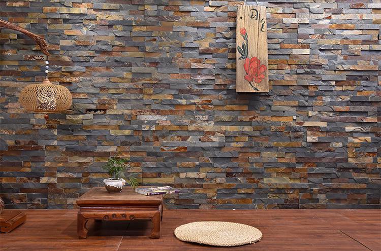
Prioritize quartzite and dense slate when you need proven UV and thermal stability. Quartzite models such as Alaska Gray and Glacier White and slate options like Carbon Black provide low porosity and strong UV resistance, making them the first choice for full-sun façades. Choose natural cleft or split-face finishes over thin topical coatings so the pigment depth remains integral to the stone and resists surface erosion.
Specify panel geometry and mass to reduce edge weathering and thermal shock: standard Top Source panels measure 150 x 600 mm or 150 x 550 mm with thickness from 1.0–2.5 cm (upgrade to 3.5 cm for premium rough sections). Flat panels weigh about 30–40 kg/m² and rough panels ~55 kg/m²; place heavier sections where rapid temperature swings occur to improve thermal buffering. Require same-quarry vein material and matching L-corners to eliminate visible color mismatch across large façades.
- Core inventory examples: Alaska Gray (Quartzite), Glacier White (Quartzite), Carbon Black (Slate).
- Preferred finishes: natural cleft, split-face, seamless interlock.
- Panel spec: 150 x 600 mm or 150 x 550 mm; thickness 1–2.5 cm (up to 3.5 cm premium).
Design and installation practices that prevent outdoor color loss
Control water, salts, and thermal movement at design stage. Provide a drained substrate, continuous air gap, and expansion joints so moisture does not lodge behind the veneer and migrate salts to the surface, which accelerate surface degradation and discoloration. Install proper flashing and drip edges sized for the exposure—standard caps use a 3″ drip edge; high-exposure designs use 8–9″ full-width caps to deflect driven rain and protect crowns.
For high-heat features, follow fire-specific specs: line the firebox with 1¼” (1.25″) firebrick compliant with ASTM 1261 and bond with refractory cement or FireRock adhesive mortar. Use noncombustible stone veneers and keep 1″ clearance to combustibles where codes require. Use Top Source interlocking Z-shape/S-shape panels with CNC diamond-blade precision to hide vertical joints and reduce water ingress, and select breathable, UV-stable penetrating sealers—apply per manufacturer instructions to avoid organic pigments that can fade or yellow under UV.
- Substrate and load: design for 30–40 kg/m² for flat panels and ~55 kg/m² for rough panels; verify backing supports those loads.
- Firebox specification: install 1¼” firebrick (ASTM 1261) with refractory cement or FireRock adhesive where required.
- Drainage and flashing: incorporate step-up/down flashing with an air gap and weep details so trapped water can escape.
- Quality control: require pre-shipment visual verification and same-batch quarry sourcing to ensure delivered color matches the project sample.
Cleaning Moss and Algae: Maintenance Tips for Shaded Fireplaces
Targeted inspection and low-impact cleaning preserve stone veneer, prevent mortar loss, and protect the noncombustible firebox lining required by code.
Pre-clean inspection: identify stone type, panel joints, and firebox boundaries
Confirm the cladding material and panel specs before you touch the surface: Natural Stacked Stone panels typically measure 1.0–3.5 cm thick and weigh roughly 30–55 kg/m², and interlocking Z‑Shape or S‑Shape panels rely on CNC-cut male/female edges and matching L‑corners to hide vertical joints. Document the stone type (slate, quartzite, sandstone, marble) and record photos of any biological growth and problem areas so you can compare before/after condition and verify whether the stone is calcareous before selecting cleaners.
Map high-risk zones — shaded faces, horizontal ledges, tight vertical joints and the interface with the firebox — and verify fire-safety clearances: the firebox interior must use refractory lining (minimum 1¼” firebrick per ASTM 1261) and the hearth must extend 30″ in front and 8″ each side when level. Probe mortar and panel edges for movement; remove or secure any panel that moves more than 5 mm before cleaning to avoid dislodgement during washing or brushing.
- Record panel thickness and weight per area (1.0–3.5 cm; ~30–55 kg/m²).
- Photograph shaded faces, ledges, and the firebox interface for condition tracking.
- Confirm refractory lining (≥1¼” firebrick) and required hearth clearances (30″ front, 8″ sides).
- Check for panel movement; secure or replace panels with >5 mm play.
Safe removal: low-impact mechanical methods and approved biocide use
Start with low-impact mechanical cleaning: scrub with soft nylon brushes and use plastic scrapers to lift moss or algae without chipping thin panels (many Top Source panels run 1–2.5 cm). Never use wire brushes, chisels, or aggressive abrasive pads on interlocking edges — those tools damage CNC-cut male/female joints and cause breakage. If you use wet cleaning, test a small area first to check for spalling or joint washout.
When you need more than brushing, follow strict pressure and chemical controls. Keep pressure wash settings low: test at 500–800 psi with a 25°–40° wide-angle nozzle held 30–45 cm (12–18 in) from the surface; do a small-area test to confirm no stone damage. For chemical control use masonry-approved algicides or a controlled sodium hypochlorite dilution (example: 1:10 bleach:water for stubborn algae), allow 10–15 minutes dwell, then rinse thoroughly with low-pressure water. Do not use acidic cleaners on calcareous stones such as marble or some sandstones; always trial-clean an inconspicuous panel and shield surrounding vegetation and mortar joints to limit runoff exposure.
- Mechanical tools: soft nylon brush, plastic scraper only.
- Pressure-wash limits: 500–800 psi; 25°–40° nozzle; 30–45 cm distance; test first.
- Biocide example: sodium hypochlorite 1:10 dilution, 10–15 minute dwell, then rinse.
- Material caution: avoid acids on calcareous stone; test cleaners on a hidden panel.
- PPE and containment: wear chemical-resistant gloves, eye protection, and cover combustibles; collect runoff where local rules require it.
Post-clean repairs, protective treatment, and routine schedule
After cleaning, replace or reseat any loose panels and repoint open joints with an exterior-grade, noncombustible mortar. In areas adjacent to the firebox or where temperatures exceed normal exterior exposure, set joints and anchors with refractory cement or FireRock Adhesive Mortar to maintain heat resistance and bond integrity. Do not apply polymeric or topical sealers inside the firebox or within the primary combustion zone — treat only the exposed cladding outside the noncombustible barrier.
Protect the cladding with a breathable silane/siloxane water repellent approved for natural stone; expect coverage around 4–6 m² per liter depending on porosity and record vendor cure times after a small absorption test. Inspect shaded faces every 6 months, remove biological regrowth as found, and plan repellent reapplication every 2–5 years — shorten the interval in high-salinity or year-round-humid regions. Reduce recurring moisture by trimming overhanging vegetation, assuring proper drainage and flashing at shelf ledges, and using interlocks and matching L‑corners to minimize exposed vertical joints and water ingress.
- Repair: reset panels, repoint with noncombustible mortar; use refractory cement/FireRock next to firebox.
- Sealer: breathable silane/siloxane; test absorption; expect ~4–6 m² per liter coverage.
- Application limit: never seal inside the firebox or primary combustion zone.
- Schedule: inspect every 6 months; reapply repellent every 2–5 years; shorten interval in coastal or humid climates.
- Design fixes: trim vegetation, improve drainage and flashing, use L‑corners and interlocks to reduce joint exposure.

The Role of Drip Caps in Preventing Water Entry Behind the Stone
A correctly specified and installed drip cap prevents moisture ingress behind stacked stone, protecting adhesive bonds, the WRB, and structural substrates.
How drip caps redirect water at the stone–substrate interface
Drip caps create a negative-drip profile that breaks surface tension and forces runoff clear of the stone cladding and the drainage plane behind it. Forming a turned-down hem at the lip and projecting the front edge past the stone face ensures water sheds away instead of clinging to the panel edge; standard practice calls for a hem minimum of 6 mm and a front projection of 10–15 mm so water falls free of the cladding rather than tracking back into the cavity.
Keep the drainage cavity continuous and clear: maintain a 6–12 mm air/drainage gap behind ledgestone panels so any water that reaches the cavity moves downward to the drip cap and exits through designed weep paths. Place a horizontal drip cap at every course break where a continuous cavity or WRB terminates, including at Z-shape and S-shape interlocks and at matching L-corners, to stop lateral water migration at transitions.
- Hem the drip lip minimum 6 mm to break surface tension and prevent cling-back.
- Project the drip 10–15 mm beyond the outer face of stacked stone panels.
- Maintain 6–12 mm continuous air/drainage gap behind panels for positive drainage to the drip cap.
- Install horizontal drip flashing at every horizontal joint, including Z/S interlocks and L-corners.
Recommended materials, profiles, and minimum thicknesses for exterior drip caps
Choose materials to match exposure. Use 304 stainless steel for general exterior locations and upgrade to 316 stainless or copper in coastal, GCC, or high-salinity sites. For non-marine contexts you may specify PVDF/Kynar-coated aluminum when the local durability expectations and coating warranty support the exposure. Design profiles with a 20–30 mm back leg that laps over the WRB, a hemmed drip of 6 mm, and a 10–15 mm front projection; form a 3–5 mm drip gap at the lip so water breaks free cleanly.
Follow minimum thickness guidance to avoid premature deformation and galvanic issues: stainless steel typically 0.6–0.8 mm (approx. 24–26 gauge), PVDF-aluminum minimum 0.7 mm, and copper 0.7–1.0 mm depending on profile and spans. Detail laps to overlap adjacent flashing by at least 50 mm (2 in) and integrate drip caps with through-wall flashing at changes in plane. For 2026 specifications, require compatibility with stone adhesives and site sealants to prevent chemical attack and galvanic corrosion.
- Material: 304 SS standard; 316 SS or copper for coastal/GCC/high-salinity exposure.
- Prefinished: PVDF/Kynar-coated aluminum acceptable in non-marine exposures; specify coating warranty.
- Minimum thickness: stainless 0.6–0.8 mm (24–26 ga); PVDF aluminum ≥0.7 mm; copper 0.7–1.0 mm by profile.
- Profile: 20–30 mm back leg over WRB, 6 mm hem, 10–15 mm projection, 3–5 mm drip gap.
- Lap: minimum 50 mm (2 in) overlap; integrate with through-wall flashing at plane changes.
- Specify metal/coating compatibility with stone adhesives and sealants to avoid chemical attack and galvanic corrosion.
Installation steps: flashing integration, fastening patterns, and sealant practice
Prepare the wall and verify a continuous WRB/drainage plane before you set any drip flashing. Ensure the substrate plane is sound, plumb, and true where the drip cap will seat; correct local irregularities so the back leg bears evenly over the WRB. Slip the drip cap under the WRB or lath with a 50 mm lap and seal the back leg with factory-approved flashing tape or a full-coverage membrane when the system requires it, keeping a clear path for water to reach the drip.
Fasten the drip cap at 200–300 mm (8–12 in) centers using corrosion-resistant fasteners and neoprene or EPDM washers; specify 316 stainless fasteners in corrosive environments. Seal end laps and terminations with a neutral-cure elastomeric sealant compatible with both metals and stone; confine sealant to lap zones and use minimal beads to avoid visible smears on the face. Provide continuous weep paths below the drip cap and test drainage by flooding the cavity or performing a hose test before you install stone. For Top Source interlocking Z/S panels and L-corners, install continuous horizontal drip flashing behind each course break and at all transitions to maintain an uninterrupted drainage plane.
- Pre-install: confirm continuous WRB/drainage plane; make substrate plumb and sound where drip seats.
- Flashing integration: slip drip under WRB with 50 mm lap; seal back leg with approved tape or membrane.
- Fastening: 200–300 mm (8–12 in) centers; use corrosion-resistant fasteners and neoprene/EPDM washers; specify 316 SS in corrosive sites.
- Joints: seal end laps and terminations with neutral-cure elastomeric compatible with metal and stone; keep beads minimal and confined to lap zones.
- Weeps and testing: provide continuous weep paths below the drip; perform a cavity flood or hose test prior to stone installation.
- Top Source panels: for Z/S interlocks and L-corners, install continuous horizontal drip flashing at every course break and transition.
Conclusion
Correct stone selection, substrate waterproofing, and freeze–thaw detailing prevent moisture intrusion and delamination that lead to structural failures. Those steps protect occupant safety, help meet OSHA and local code requirements, and extend the service life of the fireplace cladding.
Start by auditing your current fireplace details against the freeze–thaw detailing and waterproofing checklist in this guide. For certified samples, spec sheets, and pre-shipment visuals, contact Top Source Stone to review project requirements and secure factory-verified materials.
Frequently Asked Questions
What is the best natural stone for an outdoor fireplace?2. Can exterior stone handle heavy rain and snow cycles?3. Do I need to seal an outdoor stone fireplace more often?4. How to prevent stone from falling off an outdoor fireplace?5. Best adhesive for extreme outdoor temperatures?
The provided research states that approved exterior fireplace surfacing materials include fire-rated brick, tile, or natural stone, but it does not identify a single “best” natural stone. The critical requirements are that exposed materials be noncombustible, properly supported with no combustible material against the underside, and installed to meet code dimensions and clearances. Choose a natural stone product that is specified for fireplace/exterior use and install it on a properly engineered support system in compliance with local code.
Can exterior stone handle heavy rain and snow cycles?
Yes when installed to address weather and thermal movement: the research emphasizes robust foundations (a 4″–8″ reinforced concrete pad on a 4″–8″ crushed aggregate base), incorporation of expansion joints to prevent cracking from moisture and thermal cycles, and proper backing/support so the stone can tolerate freeze/thaw and thermal stress. Precast systems also use air spaces between firebrick and molds to allow cooling and reduce structural failure risk from thermal expansion.
Do I need to seal an outdoor stone fireplace more often?
The provided research does not address sealing frequency. The material focuses on selection of noncombustible materials, structural foundations, expansion joints, and appropriate adhesives for high-heat and weather exposure; it does not provide guidance on whether or how often to apply sealers.
How to prevent stone from falling off an outdoor fireplace?
Prevent detachment by using noncombustible materials installed on proper structural support and foundations, incorporating expansion joints for movement control, and using adhesives and mortars formulated for the application. For areas exposed to the firebox, the research specifies refractory cement or purpose-made adhesive mortars (e.g., FireRock Adhesive Mortar) rather than standard mortar, and also highlights that precast systems include air spaces and engineered supports to avoid failure from thermal expansion.
Best adhesive for extreme outdoor temperatures?
The research specifies that standard mortar cannot withstand the extreme thermal stress of outdoor fireplaces; use refractory cement and purpose-formulated products such as FireRock Adhesive Mortar for high-heat zones. These materials are designed to bond under sustained high temperatures and rapid thermal cycling where ordinary mortar would degrade or crack.