Eine Unterbaubeleuchtung, die ohne präzise Blendschutz- und Verkabelungsplanung installiert wird, führt zu Nacharbeiten, verzögert Übergaben und birgt das Risiko von Inspektionsfehlern, die kostspielige Bußgelder nach sich ziehen. Bei steinverkleideten Rückwänden verstärken falsch platzierte Strahlwinkel und die falsche Farbtemperatur Texturunstimmigkeiten, legen Nähte frei und erzeugen sichtbare Staub- und Schattenartefakte, die Kunden zu Änderungsaufträgen und Garantieansprüchen veranlassen – Probleme, die Budgets und Zeitpläne hart belasten.
Dieser Leitfaden fungiert als praxistaugliche SOP für Designer, Installateure und Gebäudeteams: Er erläutert, warum gebündeltes Licht gestapelten Steinen schmeichelt, wie man die LED-Farbtemperatur für warme oder kühle Steine wählt und – was am wichtigsten ist – bietet Schritt-für-Schritt-Anleitungen zur Positionierung von LED-Streifen, um starke Blendung und sichtbare Nähte zu vermeiden. Sie finden Montagevorlagen, empfohlene Lumenbereiche und Abstrahlwinkel, Dimmerstrategien zum Wechsel von der Aufgabe zur Stimmung sowie Verkabelungspläne für die Stromführung im Voraus Steininstallationund eine kurze FAQ für häufige Entscheidungen vor Ort. Nutzen Sie die Checklisten und Diagramme hier, um Überraschungen vor Ort zu vermeiden, Genehmigungen zu beschleunigen und Steinoberflächen zu liefern, die unter realen Lichtverhältnissen und auf Kundenfotos konsistent aussehen.
Warum ist Raking Light der beste Freund der Stacked-Stone-Textur?
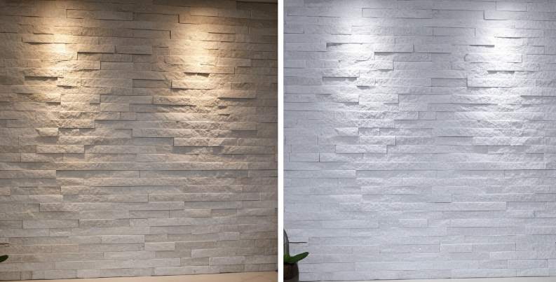
Streiflicht verwandelt Oberflächenvariationen in messbare visuelle Tiefe, verbessert die ästhetische Konsistenz und reduziert Nacharbeiten bei großen Steinstapelinstallationen.
Wie streifendes Licht Relief, Schatten und natürliche Farben hervorhebt
Streiflicht streift den Stein in einem niedrigen Winkel und erzeugt Mikroschatten in Spalten und Glanzlichter auf erhöhten Leisten, wodurch die wahrgenommene Tiefe auf geteilten Flächen und erhöht wird Ledgesteinplatten. Wenden Sie diese Technik auf Platten mit einer Dicke von 10–35 mm an (Standard 1,0–2,5 cm, Premium bis 3,5 cm), um die Schattentrennung zu maximieren und gleichzeitig eine scharfe Kantendefinition zu erhalten.
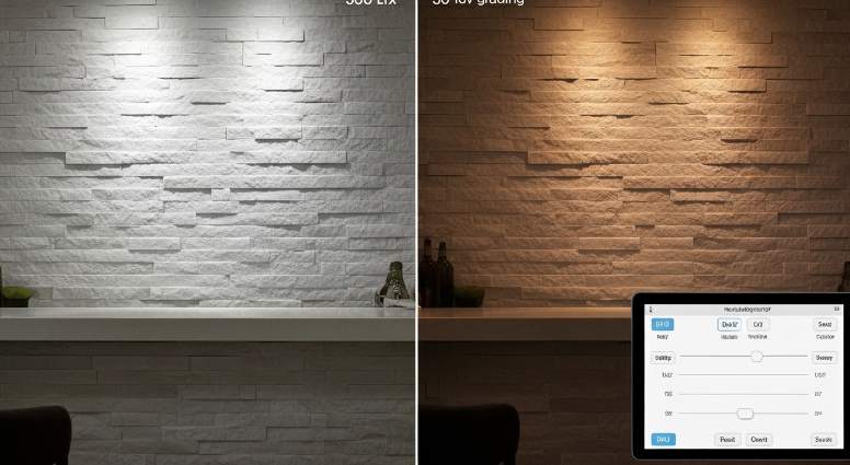
Geben Sie Quellen mit hohem CRI (CRI ≥ 90) an, damit die wahre Farbtontreue des Steins auch bei großen Auflagen sichtbar bleibt, und fordern Sie für Projektaufträge die Steinbruchkonsistenz derselben Charge (95 % Farbtoneinheitlichkeit). Passen Sie die entsprechende Farbtemperatur an die Steinfamilie an: 2700–3000 K für warme Quarzit- oder Sandsteintöne und 3500–4000 K für kühle Grau- und Weißtöne, um natürliche Kontraste zu bewahren und verwaschene Erscheinungen zu vermeiden.
- Zielplattenstärke: 10–35 mm (1,0–3,5 cm) für beste Weideergebnisse.
- Lichtqualität: CRI ≥ 90; Für große Erhebungen ist eine Farbtongleichmäßigkeit bei derselben Charge von ≥ 95 % erforderlich.
- CCT-Richtwert: 2700–3000 K (warme Steine); 3500–4000 K (kühle Steine).
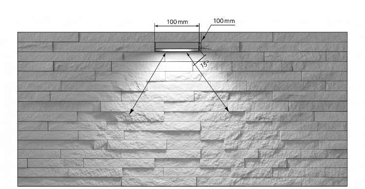
Montagegeometrie und Abstrahlwinkelregeln für effektives Abstrahlen (Platzierung, Abstand, Winkel)
Position fixtures parallel to the Wandfläche with a low tilt so light travels across the stone rather than into it. For highly irregular textures place the fixture 50–150 mm (2–6 inches) from the stone to avoid hard, distracting shadows while keeping the grazing effect. Use narrow to medium beam angles—10°–25°—to emphasize texture; wider beams will wash the surface and reduce three-dimensionality.
For long Akzentwände run continuous linear fixtures (continuous battens or asymmetric linear optics) along the wall length instead of spaced spot fixtures to maintain a uniform shadow gradient. For top-down grazing place the fixture within the top 10–15% of wall height for an uninterrupted shadow fall; use side grazing for vertical features and at corners with matching L-corners to preserve consistent edge definition.
- Distance: 50–150 mm (2–6 in) from highly irregular stone surfaces.
- Beam angle: 10°–25° for pronounced texture; wider angles for softer effect.
- Placement: within top 10–15% of wall height for top-down grazing; run fixtures continuously for long walls.
Fixture, IP and structural specifications for interior and exterior raking installations
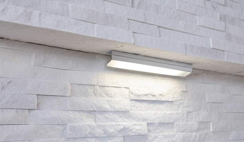
Wählen Sie die Leuchtentypen je nach Umgebung aus: Verwenden Sie lineare LED-Latten mit niedrigem Profil oder asymmetrische Wandleuchten für den Innenbereich und entscheiden Sie sich für Leuchten mit Schutzart IP65–IP66 und Halterungen aus rostfreiem Edelstahl in Marinequalität für freiliegende Außenwände. Für durchgehende Linien verwenden Sie 24-V-DC-LED-Streifen, die in Aluminiumkanälen mit Diffusoren montiert sind, um Nähte zu verbergen und Blendung zu verhindern. Verwenden Sie für Einbauten vor Ort dimmbare 120/230-VAC-Treiber, wenn die Stromverteilung dies erfordert. Geben Sie dimmbare Treiber und kompatible Steuerprotokolle (0–10 V, DALI oder PWM) an, wenn Sie Kontrastabstimmung oder Szenensteuerung benötigen.
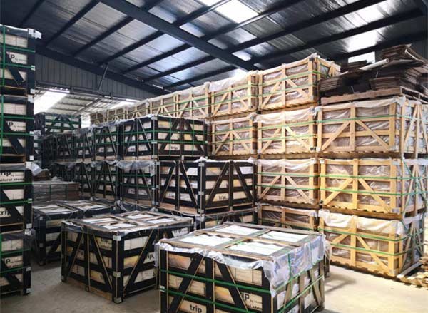
Berücksichtigen Sie das Plattengewicht bei der Gestaltung des Untergrunds und der Anker: Standard-Flachplatten wiegen etwa 30–40 kg/m² und raue Platten können bis zu 55 kg/m² erreichen. Verwenden Sie daher mechanische Anker und Stützschienen, die für diese Belastungen ausgelegt sind, anstatt sich nur auf Klebstoff zu verlassen. Für Beschaffung und Logistik ist eine visuelle Überprüfung vor dem Versand, die Bestätigung der Panelgrößen (150 × 600 mm oder 150 × 550 mm) und die Bestellung passender L-Ecken erforderlich, damit die Beleuchtungsergebnisse über die Übergänge hinweg konsistent bleiben.
- Innenausstattung: lineare Latten mit niedrigem Profil oder asymmetrische Grazer; Verwenden Sie Aluminiumkanäle + Diffusoren für Nähte und Blendschutz.
- Außenleuchten: Schutzart IP65–IP66; Edelstahlhalterungen in Marinequalität für Küstenstandorte oder Standorte mit hohem Salzgehalt.
- Power options: 24 V DC LED strips for continuous lines; 120/230 VAC dimmable drivers for distributed fixtures. Specify 0–10 V, DALI, or PWM control when dimming precision matters.
- Structural: design anchors and rails for 30–40 kg/m² (flat) or ≈55 kg/m² (rough) panels; do not rely on adhesive alone for permanent installations.
- Procurement checklist: require same-batch quarry consistency (≥95% hue uniformity), confirm panel dimensions (150×600 mm or 150×550 mm), and order matching L-corners.
Choosing the Right LED Color Temperature for Warm vs. Cool Stones
Choose LED kelvin, CRI, optics and wiring to preserve stone color and texture while minimizing field rework and warranty claims.
Match LED Kelvin and CRI to stone tone and inventory examples
Match color temperature to the stone’s inherent undertones so the material reads as the quarry intended. For warm-tone stones such as California Gold, Golden Honey, Gold Rush and Copper Canyon, select 2700K–3000K to preserve amber and gold highlights. For neutral stones use 3000K–3500K for balanced rendering. For cool-tone stones like Alaska Gray, Glacier White, Sierra Blue and Carbon Black, aim 3500K–5000K depending on whether you want a crisp, contemporary look or a neutral presentation.
Specify color fidelity to prevent batch-to-batch surprises: require CRI ≥ 90 and MacAdam 3-step or better so installers reproduce hues consistently across long runs and replacement panels. For warm stones demand a high R9 (≥ 50) or a saturated color index to retain red and amber undertones that warm light reveals.
- Warm stones: 2700K–3000K; require CRI ≥ 90 and R9 ≥ 50.
- Neutral stones: 3000K–3500K; CRI ≥ 90 and MacAdam ≤ 3-step.
- Cool stones: 3500K–5000K; CRI ≥ 90 for accurate grays and blues.
- Field test: stage 2700K, 3000K and 4000K at night on a 1–2 m sample wall to confirm perceived warmth and highlight behavior.
Select fixture type, optics and mounting for effective grazing on stacked stone
Use grazing light to skim the stone face and reveal texture; choose linear aluminum profiles with asymmetric lenses or narrow-beam adjustable spots to create controlled shadows on ledgestone. Position fixtures directly above or to the side of the plane and run continuous linear profiles on long walls to avoid scalloped light patterns. For highly textured faces keep fixtures slightly farther from the wall to soften harsh shadowing.
Select optics and mounting to balance contrast and legibility. Use narrow beams (10°–30°) or asymmetric optics to emphasize relief; avoid wide 120° diffusers when you want true grazing. For outdoor or humid environments pick IP65 or higher-rated fixtures with corrosion-resistant housings for Gulf and coastal projects to protect against salinity and moisture.
- Fixture types: linear aluminum channels with diffusers, asymmetric lenses, or adjustable narrow-beam spots.
- Beam angles: 10°–30° narrow beams or asymmetric optics; avoid 120° wide lenses for grazing.
- Mounting distance: 20–50 mm for low-relief faces; 50–150 mm for highly irregular, rough faces to reduce harsh contrast.
- Placement: mount directly above or to the side of the wall plane; use continuous runs to maintain even texture emphasis on long walls.
- Outdoor/humid spec: IP65+ and corrosion-resistant housings for coastal/Gulf projects.
Electrical, lumen density and dimming guidelines for strips and linear luminaires
Plan voltage, lumen density and wiring before you ship stone to avoid rework. Use constant-voltage 12V or 24V systems and prefer 24V for runs longer than 5 m to reduce voltage drop. Target 8–24 W/m and roughly 800–1,600 lm/m depending on relief: specify the higher end for deep, rugged textures and the lower end for subtle ledgestone faces.
Design electrical runs and controls for reliability: limit single-run length to 5–10 m for 12V and 10–20 m for 24V, and inject power every 5–10 m on long runs. Use 18 AWG for short runs (<5 m), 16 AWG for medium runs (5–15 m) and 14 AWG for longer feeders (>15 m). Size drivers with at least 20% headroom and include surge protection for coastal installations. Choose flicker-free drivers compatible with 0–10V, DALI, or PWM/DMX and test dimming curves on a stone sample before full installation.
- Voltage: constant-voltage 12V or 24V; prefer 24V for runs >5 m.
- Power & lumens: 8–24 W/m; ~800–1,600 lm/m (use higher values for deep relief).
- Run length: 5–10 m max for 12V; 10–20 m max for 24V; inject power every 5–10 m on long runs.
- Wire gauge: 18 AWG (<5 m), 16 AWG (5–15 m), 14 AWG (>15 m feeders).
- Driver sizing: allow ≥20% headroom above calculated load; include surge protection for saline/coastal sites.
- Controls: specify flicker-free drivers compatible with 0–10V, DALI or PWM/DMX; validate dimming curves on-site with a sample wall.
Premium Stacked Stone — Faster Profits
How to Position LED Strips to Avoid Harsh Glare and Expose Seams?
Place and specify lighting to protect finished stone appearance, reduce field rework, and preserve installation margins with predictable grazing and seam definition.
Plan mounting geometry for effective grazing and seam emphasis
Positionieren Sie die LED-Streifen oben oder seitlich, sodass das Licht die Steinoberfläche streift. Zielen Sie auf einen Streifwinkel von etwa 10°–30° zur Wandebene, um die Textur hervorzuheben, ohne sie abzuflachen. Halten Sie einen Montageversatz zwischen 25–150 mm (1–6 Zoll) ein; Beginnen Sie bei stark unregelmäßigen Felsvorsprüngen bei 75–150 mm (3–6 Zoll), um tiefe Schattengruben abzumildern und gleichzeitig das Oberflächenrelief lesbar zu halten.
Wenn Sie einen Nahtkontrast benötigen, platzieren Sie schmale Träger oder sekundäre Seitenläufe, die an vertikalen Fugen ausgerichtet sind, und verwenden Sie durchgehende Oberläufe zur horizontalen Betonung mit intermittierenden Seitenläufen, wenn es auf die Nahtdefinition ankommt. Markieren Sie Z- oder S-förmige Plattenverbindungen und L-Ecken auf den Grundrisszeichnungen, bevor Sie die Kanäle befestigen, damit die Vorrichtungen, Kanäle und Endprofile übereinander ausgerichtet sind corners and avoid unexpected hot spots at panel transitions.
- Grazing angle: 10°–30° from wall plane.
- Mounting offset: 25–150 mm (1–6 in); use 75–150 mm for very irregular textures.
- Plan narrow side runs at vertical seams; draw Z/S joints on layout.
- Specify matching L-corners and end profiles to avoid misaligned hot spots.
Choose LED strip characteristics: voltage, density, color and IP rating
Select 24 V strips for runs longer than 5 m to reduce voltage drop; use 12 V only for short accents under 5 m. Pick LED density to match the wash: 60 LEDs/m delivers textured accent with visible point sources, while 120 LEDs/m or higher produces a smoother wash suitable behind a diffuser. Use the rule I (A) = P (W) ÷ V (V) when sizing runs and drivers, and plan common power densities like 4.8 W/m, 9.6 W/m or 14.4 W/m into that calculation.
Specify color temperature and color rendering that flatter the stone: 2700–3500 K (warm) enhances Naturstein tones, 3000–3500 K brightens without a clinical look, and require CRI ≥ 90 for accurate color. For wet or exterior locations choose IP65 or IP67 rated strips and sealed channels; for indoor, climate-controlled walls use IP20 strips inside enclosed profiles.
- Voltage: 24 V for >5 m runs; 12 V for <5 m accents.
- LED density: 60 LEDs/m for textured accents; 120+ LEDs/m for smooth wash.
- Power densities: 4.8 W/m, 9.6 W/m, 14.4 W/m — calculate current per run (I = P ÷ V).
- Color: 2700–3500 K recommended for most stone; CRI ≥ 90.
- IP: IP65/IP67 for exterior/wet; IP20 acceptable indoors when enclosed.
Specify profiles, diffusers and glare-control accessories
Wählen Sie abgewinkelte Aluminiumkanäle (0°, 15°, 30°), um das Licht zu lenken und den streifenden Einfall zu kontrollieren. Wählen Sie den Winkel, der die gewünschte Schattentiefe erzeugt. Bringen Sie mattierte Diffusoren an, um Dioden-Hotspots abzumildern, und verwenden Sie Mikroprismen- oder Lamellenabdeckungen, wenn Sie die wahrgenommene Blendung reduzieren und gleichzeitig die Oberflächenstruktur bewahren müssen.
Platzieren Sie schmale Balkenkanäle oder freiliegende lineare Vorrichtungen an den Nähten, um Mörtellinien freizulegen, und gleichen Sie sie mit breiteren oberen Streifzügen aus. Vertiefen Sie flache Kanäle in Laibungen oder hinter Steinvorsprüngen, um die Lichtquelle zu verbergen und eine direkte Sichtverbindung zu den Dioden zu gewährleisten. Verwenden Sie Verdunklungsband oder interne Blenden in den Profilen, um zu verhindern, dass Licht auf angrenzende Oberflächen gelangt, und um die Beleuchtung auf die Steinoberfläche zu fokussieren.
- Kanäle: abgewinkeltes Aluminium 0°, 15°, 30° zur Kontrolle des Abstreifens.
- Diffusoren: mattiert zum Erweichen; Mikroprisma oder Lamellen zur Blendungskontrolle.
- Nahtstrategie: schmaler Strahlkanal an der Stoßstelle + breitere obere Streifung.
- Verdeckung: Low-Profile-Kanäle in Laibungen oder hinter Überhängen versenken.
- Lichtkontrolle: Bringen Sie Verdunklungsband oder interne Leitbleche an, um Undichtigkeiten zu verhindern.
Elektrische Dimensionierung, Verdrahtungswege und Steuerungsstrategie
Berechnen Sie den Strom pro Durchgang mit I (A) = P (W) ÷ V (V) und berücksichtigen Sie bei der Dimensionierung des Netzteils 20–25 % Treiberspielraum. Verwenden Sie 18 AWG für kurze 24-V-Strecken bis etwa 3–5 m, 16 AWG für Strecken bis 8–10 m und 14 AWG oder parallele Einspeisungen für längere oder leistungsstärkere Stromkreise, um den Spannungsabfall zu begrenzen.
Plan feed points every 5–10 m or use end- and mid-point feeds to maintain even brightness across long walls. Select dimming protocols that match the driver and control system: use PWM-capable drivers for DMX/DALI/PWM setups; choose 0–10 V or DALI for commercial integration where smooth ramping and presets are required. Always include overcurrent protection (fuse/breaker), accessible disconnects, and meet local code and IP sealing for outdoor installations.
- Sizing: I = P ÷ V; add 20–25% headroom on driver capacity.
- Wire gauge: 18 AWG up to 3–5 m, 16 AWG up to 8–10 m, 14 AWG for longer/high-power runs.
- Feed strategy: feed every 5–10 m or use parallel/mid-point feeds to avoid dimming.
- Controls: PWM drivers for DMX/DALI; 0–10 V or DALI for commercial presets.
- Safety: add fuses/breakers, accessible disconnects, and follow local electrical code.
Commissioning, measurement and on-site troubleshooting
Target wall illuminance around 100–300 lux for accent work and verify with a lux meter; adjust distance or angle until uniformity meets the design intent. Measure voltage at strip ends and keep voltage drop under about 2–5%; if you measure excessive drop, add parallel feeds or increase conductor size.
If you see glare or diode hotspots, add a frosted diffuser or move the strip 25–50 mm (1–2 in) further from the wall. If banding appears, switch to higher LED density or stagger dual runs. Check color consistency with a colorimeter and confirm all strips come from the same CCT bin and manufacturer batch. Document final strip positions, feed locations, driver models and dimmer presets on the handover sheet for future service and warranty work.
- Illuminance: aim 100–300 lux for accent; verify with a lux meter.
- Voltage drop: keep under ~2–5%; measure at strip ends.
- Glare fixes: add frosted diffuser or increase strip-to-wall distance 25–50 mm.
- Banding fixes: increase LED density or stagger dual runs.
- Color check: use a colorimeter; confirm same CCT bin and batch.
- Handover: record positions, feed points, driver models and dimmer settings.
Using Dimmer Controls to Transition from Task Lighting to Mood Lighting
Correct dimming and grazing preserve color, avoid flicker, and allow rapid switch between task and mood lighting for Stapelte Steininstallationen.
Select a dimming protocol and hardware that matches LED fixtures
Match the dimmer protocol to the driver. Use 0–10V or DALI drivers where you need reliable commercial zoning, addressability, and scene recall; pair those drivers with their matching controllers. Use trailing-edge (ELV) dimmers for most modern LED drivers; avoid leading-edge (triac) on low-wattage LED runs because it may cause flicker. Verify PWM frequency at the driver output is above 1 kHz to prevent visible strobing at low dim levels.
Specify dimmer electrical ratings and compliance before installation. Require dimmers that support LED loads down to 5 W per channel or allow a manufacturer-recommended dummy load. Confirm maximum channel current and total circuit VA against the driver and fixture datasheets, and pick UL/CE/IEC-listed components. Test one sample fixture and driver combination from the manufacturer’s compatibility list before large-scale deployment.
- Protocol: choose 0–10V for simple analog control (two control wires per run) or DALI for a digital bus with addressing and scene recall.
- Driver match: select drivers explicitly rated for the chosen protocol and confirm PWM >1 kHz at low dim levels.
- Dimmer specs: require per-channel support to 5 W or supply a dummy load; verify max channel current and total VA.
- Compliance & testing: use UL/CE/IEC-listed dimmers/drivers and test a representative sample before roll-out.
Define light levels and color temperature targets for task vs mood modes
Set measurable targets for each scene. For task lighting aim for 300–500 lux on work surfaces; use 100–200 lux for accent grazing to reveal stone texture; set mood or ambient scenes to 20–80 lux for low-key presentation. Specify CRI ≥ 90 so stone hues and veining render naturally under both task and mood settings.
Choose color temperature by function and material. Use 3000–3500 K for task scenes where clarity matters, and 2700–3000 K for mood scenes to warm stone tones and soften contrast. For linear grazing, size luminous output to the effect: 1,000–2,000 lm/m for high-impact accent or task, and 200–800 lm/m for subtle mood lighting. Require dimmers with a perceptual (log or gamma) dim curve and configurable fade times of 0.5–2 seconds to avoid abrupt jumps between scenes.
- Lux targets: Task 300–500 lx | Accent 100–200 lx | Mood 20–80 lx.
- Lumen guidance: Linear wall-wash 1,000–2,000 lm/m (accent/task) | 200–800 lm/m (mood).
- Color temperature: Task 3000–3500 K | Mood 2700–3000 K; keep per-project samples for final tuning.
- Color quality: CRI ≥ 90 required for accurate stone rendering.
- Dimming behavior: perceptual/log curve with 0.5–2 s fade time; avoid hard steps.
Place fixtures and configure grazing geometry for stacked stone surfaces
Mount fixtures low and close to the face to produce grazing shadows that emphasize depth. For moderate texture set fixture-to-wall distances at 2–6 in (50–150 mm); for highly irregular stone increase to 4–8 in (100–200 mm) to soften high-contrast shadows. Use narrow-to-medium beam wall-washers or adjustable spot fixtures to shape shadows precisely; continuous linear profiles give uniform grazing across panel joints when you need even texture emphasis.
Account for panel dimensions and serviceability. Plan for Top Source Stone standard panel modules (150 x 600 mm) and thicknesses from 1–3.5 cm when concealing tracks behind reveals or Z/S interlock panels to hide seams. Mount and space linear fixtures 30–60 cm on center depending on beam angle; aim lights parallel to the surface for a raking effect or offset slightly for softer relief. Use IP65-rated fixtures for exterior or damp locations, provide adequate heat dissipation for LED strips, and allow driver/dimmer access for servicing. Measure lux and uniformity with a light meter, save dimmer presets for task and mood scenes, then fine-tune distance and aim until the texture reading meets the design target.
- Mount distance: 50–150 mm (2–6 in) moderate texture; 100–200 mm (4–8 in) for heavy texture.
- Beam/spacing: narrow–medium beams; linear fixtures spaced 30–60 cm on center based on beam angle.
- Panel fit: design for 150 x 600 mm modules and 1–3.5 cm thickness; conceal tracks behind Z/S interlock reveals where possible.
- Environment: use IP65 fixtures outdoors or in damp zones; ensure thermal management and service access for drivers/dimmers.
- Verification: measure lux/uniformity, save presets, and iterate aim/distance until texture meets the design target.
Hidden Wiring: How to Plan Power for Lighting Before Installing Stone?
Plan power and service access before stone goes up to avoid rework, guarantee dimmer and driver compatibility, and protect project margins.
Select lighting system and power topology (mains vs low-voltage, driver sizing)
Choose mains (120V/240V AC) when you can locate drivers remotely in service spaces and choose low-voltage (12V/24V DC) when fixtures sit embedded directly behind or inside Steinplatten. Size branch circuits to the load: use 14 AWG on 120V circuits for typical 15A runs, step up to 12 AWG for 20A runs or long 240V feeders. Sum the total fixture watts, add 20% headroom, and select a driver that meets that continuous output; for constant-voltage systems pick 12V or 24V drivers, and for COB strips or linear arrays select constant-current drivers with the correct mA rating (for example 350mA, 700mA or as specified by the LED module).
Specify dimming type at design stage so panels and drivers match: triac/ELV for line-voltage dimming, PWM for many low-voltage LED drivers, and digital controls like 0–10V or DALI for networked systems. Choose IP65 or higher fixtures for exterior or damp locations and pick drivers rated for outdoor or enclosed-box use when you locate them outside conditioned spaces. Protect outdoor circuits with GFCI and follow local code for in-wall vs surface-rated enclosures.
- Driver sizing: Total watts × 1.2 = required driver capacity.
- Low-voltage choice: Use 12V/24V CV for tape in channels; use CC drivers for COB/linear arrays and match mA rating.
- Dimming compatibility: Lock in triac/ELV, PWM, 0–10V, or DALI at specification stage.
- Environment: Select IP65+ for exterior fixtures and GFCI-protect outdoor feeds.
Map conductor routes, junction boxes and conduit before panel installation
Locate and mark junction boxes on the substrate where installers can access them after stone installation; align access boxes to matching L-corners or removable panels that coincide with Top Source Stone seams. Specify conduit and cable types: use EMT, PVC, or liquid-tight flexible metal conduit (LFMC) to protect runs into junction boxes. Use 1/2″ trade conduit for single runs of 14–12 AWG conductors and use 3/4″ when you pull multiple conductors or run driver output and control wiring together.
Keep low-voltage runs short to limit voltage drop and maintain less than 3% drop to the furthest fixture. If a run exceeds ~10 m, calculate current (I = W/V) and upsize conductors to 12–10 AWG as required by conductor resistance and acceptable drop. Provide 40–60 mm of clear cavity behind Steinplatten for slim drivers and junctions, or plan remote driver locations inside service cabinets when cavity depth is insufficient. Label every pull at both ends: circuit ID, conductor gauge, supply voltage and control protocol so field crews avoid cutting interlocking Z/S panels during stone installation.
- Conduit sizing: 1/2″ for single 14–12 AWG; 3/4″ for multiple conductors or driver bundles.
- Voltage drop rule: Keep <3% to the furthest low-voltage fixture; upsize to 12–10 AWG if runs exceed ~10 m depending on load.
- Box clearance: Reserve 40–60 mm behind stone for slim drivers or plan remote driver locations.
- Documentation: Tag circuits, gauge, and control type at each junction.
Integrate wiring with stone system and grazing-light placement for best texture reveal
Design recesses and mounting channels around Obere Quellsteinplatte geometry before you fix panels: standard panels measure 150×600 mm (150×550 mm variant) with thickness from 10–35 mm. Pre-install aluminum LED channels or rigid mounting rails to the substrate so strips sit at a consistent distance from the stone face and hide wiring behind panels. Position linear or spot fixtures for grazing light so beams skim the surface; start with fixture-to-face offsets between 25–150 mm (1–6 inches) and tune on-site to the stone’s irregularity to avoid overly harsh shadows.
Reserve vertical or horizontal service channels behind interlocking Z- or S-shaped profiles or at L-corners so technicians access drivers and junctions without removing panels. Energize the system during commissioning and measure voltage at the furthest fixture to verify <3% drop for low-voltage circuits, test dimming for flicker under all levels, confirm IP seals on exterior fittings, and photograph wiring and junction locations for future maintenance records.
- Panel specs to plan around: 150×600 mm or 150×550 mm; thickness 10–35 mm.
- Grazing offset: 25–150 mm from face; adjust on-site for texture.
- Pre-install channels: Use aluminum channels with diffusers to control glare and conceal seams.
- Commissioning checklist: Measure voltage at furthest fixture, check dimming performance, verify IP ratings, and photograph layouts.
Abschluss
Correct placement, concealed wiring, and dimmer planning do more than shape appearance: they protect installers, ensure OSHA and local code compliance, and cut glare and electrical risks. They also extend fixture life and reduce long-term maintenance costs.
Review your current installations against the positioning and wiring checklist above, or contact Top Source Stone for a certified lighting catalog and sample kit to plan a compliant, high-performing finish.
Häufig gestellte Fragen
What color LED light is best for natural white stone?
The provided research does not specify a particular LED color. It emphasizes that grazing (raking) light — positioned to skim across the stone face — is the key factor for bringing out the texture and natural shadows of white stone.
Where should the LED strip be mounted: front or back of the cabinet?
Position the light so it achieves grazing: directly above or to the side of the Steinmauer so light travels across the face at a low angle. Whether the strip is mounted at the front or back of a cabinet is secondary to ensuring the fixture creates that low-angle skim across the stone surface.
Does under-cabinet lighting show dust on the stone texture?
The research doesn’t directly address dust, but because grazing skims the surface and emphasizes small shadows and highlights, it increases the visual contrast of texture and can make surface irregularities — including dust — more noticeable.
Can I use puck lights instead of tape lights for stone walls?
The provided research does not compare puck versus tape lights. It focuses on achieving grazing by placing the light source along the top or side so light skims across the face — which implies a continuous, well-placed source is desirable for even grazing; point sources may produce hotspots rather than a uniform skim.
Will the heat from the LED lights damage the stone sealer?
The research content does not address heat or effects on stone sealer; it only covers the visual impact of grazing light. For heat and sealer compatibility, consult product specifications from the light and sealer manufacturers.