L'illuminazione sottopensile installata senza un preciso controllo dell'abbagliamento e una pianificazione del cablaggio comporta rilavorazioni, ritardi nelle consegne e rischia di fallire le ispezioni che comportano costose sanzioni di conformità. Sugli alzatine rivestite in pietra, gli angoli del fascio fuori posto e la temperatura del colore sbagliata amplificano le incoerenze delle texture, espongono le cuciture e creano polvere visibile e artefatti d'ombra che spingono i clienti a modificare ordini e richieste di garanzia, problemi che colpiscono duramente budget e programmi.
This guide functions as a field-ready SOP for designers, installers, and facilities teams: it covers why raking light flatters stacked stone, how to choose LED color temperature for warm versus cool stones, and—most importantly—provides step-by-step instructions on how to position LED strips to avoid harsh glare and reveal seams. You will find mounting templates, recommended lumen ranges and beam angles, dimmer strategies to shift from task to mood, wiring plans for routing power before installazione in pietra, and a concise FAQ for common on-site decisions. Use the checklists and diagrams here to reduce on-site surprises, speed approvals, and deliver stone finishes that look consistent under real-world lighting and in client photos.
Why Raking Light is the Best Friend of Stacked Stone Texture?
Raking light turns surface variation into measurable visual depth, improving aesthetic consistency and reducing rework on large stacked-stone installations.
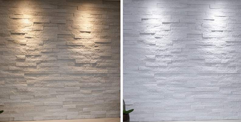
How grazing light exaggerates relief, shadow and natural color
Grazing light skims the stone at a low angle to create micro-shadows in crevices and highlights on raised ledges, increasing perceived depth on split-face and pannelli di pietra sporgente. Apply this technique to panels that measure 10–35 mm thick (standard 1.0–2.5 cm, premium up to 3.5 cm) to maximize shadow separation while preserving crisp edge definition.
Specify high-CRI sources (CRI ≥ 90) so the stone’s true hue fidelity remains visible across large runs, and require same-batch quarry consistency (95% hue uniformity) for project orders. Match correlated color temperature to the stone family: 2700–3000 K for warm quartzite or sandstone tones, and 3500–4000 K for cool grays and whites to preserve natural contrast and avoid washed-out appearances.
- Target panel thickness: 10–35 mm (1.0–3.5 cm) for best grazing results.
- Light quality: CRI ≥ 90; require same-batch hue uniformity ≥ 95% for large elevations.
- CCT guidance: 2700–3000 K (warm stones); 3500–4000 K (cool stones).
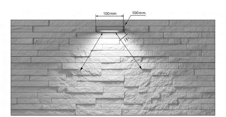
Mounting geometry and beam-angle rules for effective raking (placement, distance, angle)
Posizionare gli apparecchi parallelamente al faccia della parete con un'inclinazione bassa in modo che la luce viaggi attraverso la pietra anziché al suo interno. Per strutture molto irregolari, posizionare l'apparecchio a 50–150 mm (2–6 pollici) dalla pietra per evitare ombre dure e distraenti mantenendo l'effetto radente. Utilizzare angoli del fascio da stretti a medi, da 10° a 25°, per enfatizzare la struttura; fasci più larghi laveranno la superficie e ridurranno la tridimensionalità.
Per molto tempo pareti d'accento eseguire apparecchi lineari continui (listelli continui o ottiche lineari asimmetriche) lungo la lunghezza della parete invece di apparecchi spot distanziati per mantenere un gradiente d'ombra uniforme. Per l'effetto radente dall'alto verso il basso, posizionare l'apparecchio entro il 10–15% superiore dell'altezza della parete per una caduta d'ombra ininterrotta; utilizzare il radente laterale per elementi verticali e in angoli con angoli a L abbinati per preservare il bordo coerente definizione.
- Distanza: 50–150 mm (2–6 pollici) da superfici di pietra altamente irregolari.
- Angolo del fascio: 10°–25° per texture pronunciate; angoli più ampi per un effetto più morbido.
- Posizionamento: entro il 10–15% superiore dell'altezza del muro per il pascolo dall'alto verso il basso; far funzionare gli apparecchi ininterrottamente per pareti lunghe.
Specifiche di fissaggio, IP e strutturali per installazioni di rastrellature interne ed esterne
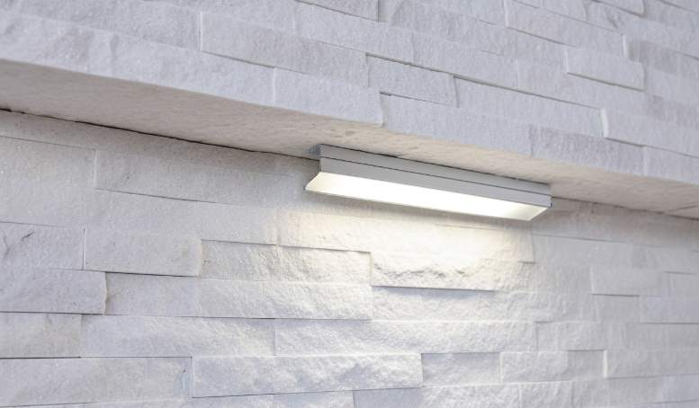
Scegli i tipi di apparecchi in base all'ambiente: utilizza listelli LED lineari a basso profilo o apparecchi di illuminazione asimmetrici radenti per interni e specifica apparecchi con grado di protezione IP65-IP66 con supporti in acciaio inossidabile di grado marino per pareti esterne esposte. Per le file continue utilizzare strip LED a 24 V DC montate su canali in alluminio con diffusori per nascondere le giunture ed eliminare i riflessi; per gli apparecchi da cantiere utilizzare driver dimmerabili da 120/230 V CA laddove la distribuzione dell'alimentazione lo richieda. Specifica driver dimmerabili e protocolli di controllo compatibili (0–10 V, DALI o PWM) quando è necessaria la regolazione del contrasto o il controllo della scena.
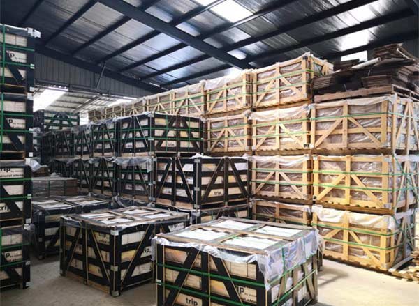
Account for panel weight when designing the substrate and anchors: standard flat panels weigh roughly 30–40 kg/m² and rough panels can reach ≈55 kg/m², so use mechanical anchors and support rails rated for those loads instead of relying on adhesive alone. For procurement and logistics require pre-shipment visual verification, confirm panel sizes (150 × 600 mm or 150 × 550 mm) and order matching L-corners so lighting outcomes remain consistent across transitions.
- Indoor fixtures: low-profile linear battens or asymmetric grazers; use aluminum channels + diffusers for seams and glare control.
- Outdoor fixtures: IP65–IP66 rating; marine‑grade stainless mounts for coastal or high-salinity sites.
- Opzioni di alimentazione: strip LED 24 V DC per file continue; Driver dimmerabili 120/230 VAC per apparecchi distribuiti. Specifica il controllo 0–10 V, DALI o PWM quando la precisione della regolazione è importante.
- Strutturale: ancoraggi e guide di progettazione per pannelli da 30–40 kg/m² (piani) o ≈55 kg/m² (grezzi); non fare affidamento solo sull'adesivo per installazioni permanenti.
- Lista di controllo per l'approvvigionamento: richiedere la consistenza della cava dello stesso lotto (uniformità della tonalità ≥95%), confermare le dimensioni del pannello (150×600 mm o 150×550 mm) e ordinare gli angoli a L corrispondenti.
Scegliere la giusta temperatura di colore del LED per pietre calde o fredde
Scegli LED Kelvin, CRI, ottica e cablaggio per preservare il colore e la struttura della pietra riducendo al minimo le rilavorazioni sul campo e le richieste di garanzia.
Abbina LED Kelvin e CRI al tono della pietra e agli esempi di inventario
Abbina la temperatura del colore alle sfumature intrinseche della pietra in modo che il materiale sembri come previsto dalla cava. Per pietre dai toni caldi come California Gold, Golden Honey, Gold Rush e Copper Canyon, seleziona 2700K–3000K per preservare i riflessi ambrati e dorati. Per le pietre neutre utilizzare 3000K–3500K per un rendering bilanciato. Per pietre dai toni freddi come Alaska Grey, Glacier White, Sierra Blue e Carbon Black, punta a 3500K–5000K a seconda che desideri un aspetto fresco e contemporaneo o una presentazione neutra.
Specifica la fedeltà dei colori per evitare sorprese lotto per lotto: richiede CRI ≥ 90 e MacAdam 3-step o migliore gli installatori riproducono le tonalità in modo coerente su lunghe tirature e pannelli sostitutivi. For warm stones demand a high R9 (≥ 50) or a saturated color index to retain red and amber undertones that warm light reveals.
- Warm stones: 2700K–3000K; require CRI ≥ 90 and R9 ≥ 50.
- Neutral stones: 3000K–3500K; CRI ≥ 90 and MacAdam ≤ 3-step.
- Cool stones: 3500K–5000K; CRI ≥ 90 for accurate grays and blues.
- Field test: stage 2700K, 3000K and 4000K at night on a 1–2 m sample wall to confirm perceived warmth and highlight behavior.
Select fixture type, optics and mounting for effective grazing on stacked stone
Use grazing light to skim the stone face and reveal texture; choose linear aluminum profiles with asymmetric lenses or narrow-beam adjustable spots to create controlled shadows on ledgestone. Position fixtures directly above or to the side of the plane and run continuous linear profiles on long walls to avoid scalloped light patterns. For highly textured faces keep fixtures slightly farther from the wall to soften harsh shadowing.
Seleziona ottica e montaggio per bilanciare contrasto e leggibilità. Utilizzare fasci stretti (10°–30°) o ottiche asimmetriche per enfatizzare il rilievo; evita i diffusori larghi da 120° quando vuoi una vera radenza. Per ambienti esterni o umidi, scegli apparecchi con grado di protezione IP65 o superiore con custodie resistenti alla corrosione per progetti del Golfo e costieri per la protezione da salinità e umidità.
- Tipologie di apparecchi: canali lineari in alluminio con diffusori, lenti asimmetriche o faretti orientabili a fascio stretto.
- Angoli di fascio: fasci stretti 10°–30° o ottiche asimmetriche; avoid 120° wide lenses for grazing.
- Distanza di montaggio: 20–50 mm per volti in bassorilievo; 50–150 mm per volti molto irregolari e ruvidi per ridurre il contrasto eccessivo.
- Placement: mount directly above or to the side of the wall plane; use continuous runs to maintain even texture emphasis on long walls.
- Outdoor/humid spec: IP65+ and corrosion-resistant housings for coastal/Gulf projects.
Electrical, lumen density and dimming guidelines for strips and linear luminaires
Plan voltage, lumen density and wiring before you ship stone to avoid rework. Use constant-voltage 12V or 24V systems and prefer 24V for runs longer than 5 m to reduce voltage drop. Target 8–24 W/m and roughly 800–1,600 lm/m depending on relief: specify the higher end for deep, rugged textures and the lower end for subtle ledgestone faces.
Progetta i percorsi elettrici e i controlli in modo affidabile: limita la lunghezza del singolo percorso a 5–10 m per 12 V e 10–20 m per 24 V e inietta alimentazione ogni 5–10 m su percorsi lunghi. Utilizzare 18 AWG per tirature brevi (<5 m), 16 AWG per corse medie (5–15 m) e 14 AWG per alimentatori più lunghi (>15 m). Driver di dimensioni con almeno il 20% di headroom e includono protezione da sovratensione per installazioni costiere. Scegli driver privi di sfarfallio compatibili con 0–10 V, DALI o PWM/DMX e testa le curve di dimmerazione su un campione di pietra prima dell'installazione completa.
- Voltaggio: tensione costante 12V o 24V; preferire 24 V per le corse >5 metri.
- Energia & lumen: 8–24 W/m; ~800–1.600 lm/m (utilizzare valori più alti per rilievi profondi).
- Run length: 5–10 m max for 12V; 10–20 m max for 24V; inject power every 5–10 m on long runs.
- Wire gauge: 18 AWG (<5 m), 16 AWG (5–15 m), 14 AWG (>15 m feeders).
- Driver sizing: allow ≥20% headroom above calculated load; include surge protection for saline/coastal sites.
- Controls: specify flicker-free drivers compatible with 0–10V, DALI or PWM/DMX; validate dimming curves on-site with a sample wall.
Premium Stacked Stone — Faster Profits
How to Position LED Strips to Avoid Harsh Glare and Expose Seams?
Place and specify lighting to protect finished stone appearance, reduce field rework, and preserve installation margins with predictable grazing and seam definition.
Plan mounting geometry for effective grazing and seam emphasis
Position LED strips above or to the side so light skims the stone face; target a grazing angle of roughly 10°–30° from the wall plane to emphasize texture without flattening it. Maintain a mounting offset between 25–150 mm (1–6 in); for highly irregular ledgestone start at 75–150 mm (3–6 in) to soften deep shadow pits while keeping surface relief legible.
Locate narrow-beam or secondary side runs aligned with vertical joints when you need seam contrast, and use continuous top runs for horizontal emphasis with intermittent side runs where seam definition matters. Mark Z- or S-shape panel joints and L-corners on layout drawings before fixing channels so fixtures, channels and end profiles align across corners and avoid unexpected hot spots at panel transizioni.
- Grazing angle: 10°–30° from wall plane.
- Mounting offset: 25–150 mm (1–6 in); use 75–150 mm for very irregular textures.
- Plan narrow side runs at vertical seams; draw Z/S joints on layout.
- Specificare gli angoli a L e i profili finali corrispondenti per evitare punti caldi disallineati.
Scegli le caratteristiche della striscia LED: tensione, densità, colore e grado IP
Select 24 V strips for runs longer than 5 m to reduce voltage drop; use 12 V only for short accents under 5 m. Pick LED density to match the wash: 60 LEDs/m delivers textured accent with visible point sources, while 120 LEDs/m or higher produces a smoother wash suitable behind a diffuser. Use the rule I (A) = P (W) ÷ V (V) when sizing runs and drivers, and plan common power densities like 4.8 W/m, 9.6 W/m or 14.4 W/m into that calculation.
Specify color temperature and color rendering that flatter the stone: 2700–3500 K (warm) enhances Pietra naturale tones, 3000–3500 K brightens without a clinical look, and require CRI ≥ 90 for accurate color. For wet or exterior locations choose IP65 or IP67 rated strips and sealed channels; for indoor, climate-controlled walls use IP20 strips inside enclosed profiles.
- Voltage: 24 V for >5 m runs; 12 V for <5 m accents.
- LED density: 60 LEDs/m for textured accents; 120+ LEDs/m for smooth wash.
- Power densities: 4.8 W/m, 9.6 W/m, 14.4 W/m — calculate current per run (I = P ÷ V).
- Color: 2700–3500 K recommended for most stone; CRI ≥ 90.
- IP: IP65/IP67 for exterior/wet; IP20 acceptable indoors when enclosed.
Specify profiles, diffusers and glare-control accessories
Scegli i canali in alluminio angolati (0°, 15°, 30°) per orientare la luce e controllare l'incidenza radente; scegli l'angolo che crea la profondità dell'ombra che desideri. Installa diffusori satinati per ammorbidire i punti caldi dei diodi e utilizza microprismi o coperture con feritoie quando è necessario ridurre l'abbagliamento percepito preservando la struttura della superficie.
Posizionare canali a fascio stretto o dispositivi lineari esposti in corrispondenza delle giunture per esporre le linee di malta e bilanciarli con percorsi più ampi in alto. Incassa i canali a basso profilo nelle traverse o dietro le sporgenze in pietra per nascondere la sorgente luminosa e mantenere le linee di vista dirette lontane dai diodi. Utilizzare nastro oscurante o deflettori interni all'interno dei profili per impedire la perdita di luce sulle superfici adiacenti e mantenere l'illuminazione concentrata sulla facciata in pietra.
- Channels: angled aluminium 0°, 15°, 30° to control grazing.
- Diffusers: frosted for softening; micro-prism or louvers for glare control.
- Seam strategy: narrow-beam channel at joint + wider top grazing.
- Concealment: recess low-profile channels into reveals or behind overhangs.
- Light control: apply blackout tape or internal baffles to prevent leaks.
Electrical sizing, wiring runs and control strategy
Calculate current per run with I (A) = P (W) ÷ V (V) and add 20–25% driver headroom when sizing the PSU. Use 18 AWG for short 24 V runs up to about 3–5 m, 16 AWG for runs up to 8–10 m, and 14 AWG or parallel feeds for longer or higher-power circuits to limit voltage drop.
Pianifica i punti di alimentazione ogni 5-10 m o utilizza le alimentazioni a punto finale e intermedio per mantenere una luminosità uniforme sulle pareti lunghe. Seleziona i protocolli di dimmerazione che corrispondono al driver e al sistema di controllo: utilizza driver compatibili con PWM per configurazioni DMX/DALI/PWM; scegli 0–10 V o DALI per l'integrazione commerciale dove sono necessarie rampe e preimpostazioni uniformi. Includere sempre la protezione da sovracorrente (fusibile/interruttore), sezionatori accessibili e soddisfare le normative locali e il sigillo IP per le installazioni esterne.
- Dimensionamento: I = P ÷ V; add 20–25% headroom on driver capacity.
- Calibro del filo: 18 AWG fino a 3–5 m, 16 AWG fino a 8–10 m, 14 AWG per corse più lunghe/ad alta potenza.
- Strategia di alimentazione: nutrire ogni 5-10 m o utilizzare alimentazioni parallele/a punto centrale per evitare l'oscuramento.
- Controls: PWM drivers for DMX/DALI; 0–10 V or DALI for commercial presets.
- Safety: add fuses/breakers, accessible disconnects, and follow local electrical code.
Commissioning, measurement and on-site troubleshooting
Target wall illuminance around 100–300 lux for accent work and verify with a lux meter; adjust distance or angle until uniformity meets the design intent. Measure voltage at strip ends and keep voltage drop under about 2–5%; if you measure excessive drop, add parallel feeds or increase conductor size.
Se noti abbagliamenti o punti caldi dei diodi, aggiungi un diffusore smerigliato o sposta la striscia di 25–50 mm (1–2 pollici) più lontano dal muro. Se compaiono bande, passare a una densità LED più elevata o scaglionare le doppie corse. Controllare la consistenza del colore con un colorimetro e verificare che tutte le strisce provengano dallo stesso contenitore CCT e dallo stesso lotto del produttore. Documenta le posizioni finali delle strisce, le posizioni di alimentazione, i modelli di driver e le preimpostazioni del dimmer sul foglio di consegna per futuri interventi di assistenza e garanzia.
- Illuminamento: puntare a 100–300 lux per l'accento; verificare con un luxmetro.
- Caduta di tensione: mantenersi sotto il ~2–5%; misurare alle estremità della striscia.
- Correzioni dell'abbagliamento: aggiungi un diffusore satinato o aumenta la distanza tra la striscia e la parete di 25–50 mm.
- Correzioni di banding: aumento della densità dei LED o scaglionamento delle doppie esecuzioni.
- Controllo del colore: utilizzare un colorimetro; confermare lo stesso contenitore e batch CCT.
- Handover: registra posizioni, punti di alimentazione, modelli di driver e impostazioni del dimmer.
Utilizzo dei controlli dimmer per la transizione dall'illuminazione operativa all'illuminazione d'atmosfera
L'attenuazione e l'effetto radente corretti preservano il colore, evitano lo sfarfallio e consentono un rapido passaggio dall'illuminazione per attività a quella d'atmosfera Installazione in pietra impilata.
Seleziona un protocollo di regolazione e un hardware adatto agli apparecchi LED
Match the dimmer protocol to the driver. Use 0–10V or DALI drivers where you need reliable commercial zoning, addressability, and scene recall; pair those drivers with their matching controllers. Use trailing-edge (ELV) dimmers for most modern LED drivers; avoid leading-edge (triac) on low-wattage LED runs because it may cause flicker. Verify PWM frequency at the driver output is above 1 kHz to prevent visible strobing at low dim levels.
Specificare i valori elettrici e la conformità del dimmer prima dell'installazione. Richiedono dimmer che supportino carichi LED fino a 5 W per canale o consentano un carico fittizio consigliato dal produttore. Verificare la corrente massima del canale e il VA totale del circuito confrontandoli con le schede tecniche del driver e dell'apparecchiatura e scegliere i componenti elencati UL/CE/IEC. Testare una combinazione campione di dispositivo e driver dall'elenco di compatibilità del produttore prima dell'implementazione su larga scala.
- Protocollo: scegliere 0–10 V per un semplice controllo analogico (due cavi di controllo per corsa) o DALI per un bus digitale con indirizzamento e richiamo di scene.
- Corrispondenza driver: seleziona i driver esplicitamente classificati per il protocollo scelto e conferma PWM >1 kHz a bassi livelli di attenuazione.
- Dimmer specs: require per-channel support to 5 W or supply a dummy load; verify max channel current and total VA.
- Compliance & testing: use UL/CE/IEC-listed dimmers/drivers and test a representative sample before roll-out.
Define light levels and color temperature targets for task vs mood modes
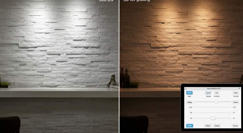
Set measurable targets for each scene. For task lighting aim for 300–500 lux on work surfaces; use 100–200 lux for accent grazing to reveal stone texture; set mood or ambient scenes to 20–80 lux for low-key presentation. Specify CRI ≥ 90 so stone hues and veining render naturally under both task and mood settings.
Choose color temperature by function and material. Use 3000–3500 K for task scenes where clarity matters, and 2700–3000 K for mood scenes to warm stone tones and soften contrast. For linear grazing, size luminous output to the effect: 1,000–2,000 lm/m for high-impact accent or task, and 200–800 lm/m for subtle mood lighting. Require dimmers with a perceptual (log or gamma) dim curve and configurable fade times of 0.5–2 seconds to avoid abrupt jumps between scenes.
- Lux targets: Task 300–500 lx | Accent 100–200 lx | Mood 20–80 lx.
- Lumen guidance: Linear wall-wash 1,000–2,000 lm/m (accent/task) | 200–800 lm/m (mood).
- Color temperature: Task 3000–3500 K | Mood 2700–3000 K; keep per-project samples for final tuning.
- Color quality: CRI ≥ 90 required for accurate stone rendering.
- Dimming behavior: perceptual/log curve with 0.5–2 s fade time; avoid hard steps.
Place fixtures and configure grazing geometry for stacked stone surfaces
Mount fixtures low and close to the face to produce grazing shadows that emphasize depth. For moderate texture set fixture-to-wall distances at 2–6 in (50–150 mm); for highly irregular stone increase to 4–8 in (100–200 mm) to soften high-contrast shadows. Use narrow-to-medium beam wall-washers or adjustable spot fixtures to shape shadows precisely; continuous linear profiles give uniform grazing across panel joints when you need even texture emphasis.
Account for panel dimensions and serviceability. Plan for Top Source Stone standard panel modules (150 x 600 mm) and thicknesses from 1–3.5 cm when concealing tracks behind reveals or Z/S interlock panels to hide seams. Mount and space linear fixtures 30–60 cm on center depending on beam angle; aim lights parallel to the surface for a raking effect or offset slightly for softer relief. Use IP65-rated fixtures for exterior or damp locations, provide adequate heat dissipation for LED strips, and allow driver/dimmer access for servicing. Measure lux and uniformity with a light meter, save dimmer presets for task and mood scenes, then fine-tune distance and aim until the texture reading meets the design target.
- Mount distance: 50–150 mm (2–6 in) moderate texture; 100–200 mm (4–8 in) for heavy texture.
- Beam/spacing: narrow–medium beams; linear fixtures spaced 30–60 cm on center based on beam angle.
- Panel fit: design for 150 x 600 mm modules and 1–3.5 cm thickness; conceal tracks behind Z/S interlock reveals where possible.
- Environment: use IP65 fixtures outdoors or in damp zones; ensure thermal management and service access for drivers/dimmers.
- Verification: measure lux/uniformity, save presets, and iterate aim/distance until texture meets the design target.
Hidden Wiring: How to Plan Power for Lighting Before Installing Stone?
Plan power and service access before stone goes up to avoid rework, guarantee dimmer and driver compatibility, and protect project margins.
Select lighting system and power topology (mains vs low-voltage, driver sizing)
Choose mains (120V/240V AC) when you can locate drivers remotely in service spaces and choose low-voltage (12V/24V DC) when fixtures sit embedded directly behind or inside pannelli in pietra. Size branch circuits to the load: use 14 AWG on 120V circuits for typical 15A runs, step up to 12 AWG for 20A runs or long 240V feeders. Sum the total fixture watts, add 20% headroom, and select a driver that meets that continuous output; for constant-voltage systems pick 12V or 24V drivers, and for COB strips or linear arrays select constant-current drivers with the correct mA rating (for example 350mA, 700mA or as specified by the LED module).
Specify dimming type at design stage so panels and drivers match: triac/ELV for line-voltage dimming, PWM for many low-voltage LED drivers, and digital controls like 0–10V or DALI for networked systems. Choose IP65 or higher fixtures for exterior or damp locations and pick drivers rated for outdoor or enclosed-box use when you locate them outside conditioned spaces. Protect outdoor circuits with GFCI and follow local code for in-wall vs surface-rated enclosures.
- Driver sizing: Total watts × 1.2 = required driver capacity.
- Low-voltage choice: Use 12V/24V CV for tape in channels; use CC drivers for COB/linear arrays and match mA rating.
- Dimming compatibility: Lock in triac/ELV, PWM, 0–10V, or DALI at specification stage.
- Environment: Select IP65+ for exterior fixtures and GFCI-protect outdoor feeds.
Map conductor routes, junction boxes and conduit before panel installation
Locate and mark junction boxes on the substrate where installers can access them after stone installation; align access boxes to matching L-corners or removable panels that coincide with Top Source Stone seams. Specify conduit and cable types: use EMT, PVC, or liquid-tight flexible metal conduit (LFMC) to protect runs into junction boxes. Use 1/2″ trade conduit for single runs of 14–12 AWG conductors and use 3/4″ when you pull multiple conductors or run driver output and control wiring together.
Keep low-voltage runs short to limit voltage drop and maintain less than 3% drop to the furthest fixture. If a run exceeds ~10 m, calculate current (I = W/V) and upsize conductors to 12–10 AWG as required by conductor resistance and acceptable drop. Provide 40–60 mm of clear cavity behind pannelli in pietra for slim drivers and junctions, or plan remote driver locations inside service cabinets when cavity depth is insufficient. Label every pull at both ends: circuit ID, conductor gauge, supply voltage and control protocol so field crews avoid cutting interlocking Z/S panels during stone installation.
- Conduit sizing: 1/2″ for single 14–12 AWG; 3/4″ for multiple conductors or driver bundles.
- Voltage drop rule: Keep <3% to the furthest low-voltage fixture; upsize to 12–10 AWG if runs exceed ~10 m depending on load.
- Box clearance: Reserve 40–60 mm behind stone for slim drivers or plan remote driver locations.
- Documentation: Tag circuits, gauge, and control type at each junction.
Integrate wiring with stone system and grazing-light placement for best texture reveal
Design recesses and mounting channels around Pannello superiore in pietra di origine geometry before you fix panels: standard panels measure 150×600 mm (150×550 mm variant) with thickness from 10–35 mm. Pre-install aluminum LED channels or rigid mounting rails to the substrate so strips sit at a consistent distance from the stone face and hide wiring behind panels. Position linear or spot fixtures for grazing light so beams skim the surface; start with fixture-to-face offsets between 25–150 mm (1–6 inches) and tune on-site to the stone’s irregularity to avoid overly harsh shadows.
Reserve vertical or horizontal service channels behind interlocking Z- or S-shaped profiles or at L-corners so technicians access drivers and junctions without removing panels. Energize the system during commissioning and measure voltage at the furthest fixture to verify <3% drop for low-voltage circuits, test dimming for flicker under all levels, confirm IP seals on exterior fittings, and photograph wiring and junction locations for future maintenance records.
- Panel specs to plan around: 150×600 mm or 150×550 mm; thickness 10–35 mm.
- Grazing offset: 25–150 mm from face; adjust on-site for texture.
- Pre-install channels: Use aluminum channels with diffusers to control glare and conceal seams.
- Commissioning checklist: Measure voltage at furthest fixture, check dimming performance, verify IP ratings, and photograph layouts.
Conclusione
Correct placement, concealed wiring, and dimmer planning do more than shape appearance: they protect installers, ensure OSHA and local code compliance, and cut glare and electrical risks. They also extend fixture life and reduce long-term maintenance costs.
Review your current installations against the positioning and wiring checklist above, or contact Top Source Stone for a certified lighting catalog and sample kit to plan a compliant, high-performing finish.
Domande frequenti
What color LED light is best for natural white stone?
The provided research does not specify a particular LED color. It emphasizes that grazing (raking) light — positioned to skim across the stone face — is the key factor for bringing out the texture and natural shadows of white stone.
Where should the LED strip be mounted: front or back of the cabinet?
Position the light so it achieves grazing: directly above or to the side of the muro di pietra so light travels across the face at a low angle. Whether the strip is mounted at the front or back of a cabinet is secondary to ensuring the fixture creates that low-angle skim across the stone surface.
Does under-cabinet lighting show dust on the stone texture?
The research doesn’t directly address dust, but because grazing skims the surface and emphasizes small shadows and highlights, it increases the visual contrast of texture and can make surface irregularities — including dust — more noticeable.
Can I use puck lights instead of tape lights for stone walls?
The provided research does not compare puck versus tape lights. It focuses on achieving grazing by placing the light source along the top or side so light skims across the face — which implies a continuous, well-placed source is desirable for even grazing; point sources may produce hotspots rather than a uniform skim.
Will the heat from the LED lights damage the stone sealer?
The research content does not address heat or effects on stone sealer; it only covers the visual impact of grazing light. For heat and sealer compatibility, consult product specifications from the light and sealer manufacturers.